Putting an autonomous forklift on a German factory floor is not a software problem. It is a legal one. The vehicle that drives itself through a warehouse is, in the eyes of the law, a machine — and before it can move a single pallet, it must pass through a certification procedure that most robotics teams never see coming.
The certification is not a checkbox at the end. It is a design constraint from the first line of code. This post walks the full path: the legal framework, the risk assessment, the functional-safety architecture, the hardware, the software, and the final CE marking.
The legal frame: Machinery Regulation (EU) 2023/1230
The rules are in transition. On January 14, 2027, Regulation (EU) 2023/1230 — the Machinery Regulation — fully replaces the Machinery Directive 2006/42/EC, with no transition period. Because it is a Regulation and not a Directive, it applies directly in every member state, including Germany, without national transposition.
The change that matters most for autonomous vehicles is how the regulation treats self-evolving behavior. The historic high-risk machinery list is split into two parts:
| Annex I part | What it covers | Conformity route |
|---|---|---|
| Part A | Safety components with self-evolving ML behavior; machinery embedding such subsystems | Third-party Notified Body required (TÜV SÜD, TÜV Rheinland) — Module B+C, H, or G |
| Part B | Electro-sensitive protective equipment (laser scanners, light curtains); safety logic units | Self-certification (Module A) only if harmonized standards are applied in full |
The consequence is sharp: if the forklift's path planning or obstacle perception uses non-deterministic, self-evolving AI that influences safety-critical stopping, self-certification is off the table. A Notified Body must assess it. This is the single most important strategic question to answer before choosing an autonomy stack.
Two more provisions deserve attention:
- Cybersecurity is now part of functional safety. Annex III requires safety-related control loops to resist external interference, and demands an immutable log of every software modification.
- "Substantial modification" makes you the OEM. Retrofit an existing manual forklift with an autonomy kit, or change kinematic limits, and the integrator assumes full OEM liability — new conformity assessment, new technical file, new CE mark.
The risk assessment: ISO 12100
Everything starts with ISO 12100, the Type A umbrella standard. It defines the three-step risk reduction method, applied strictly in order:
flowchart TD
    A["Identify hazards"] --> B["Estimate risk"]
    B --> C["Evaluate risk"]
    C --> D{"Acceptable?"}
    D -->|No| E["Step 1: Inherently safe design"]
    E --> F["Step 2: Safeguarding & protective measures"]
    F --> G["Step 3: Information for use"]
    G --> C
    D -->|Yes| H["Residual risk documented"]
The steps cannot be skipped. Inherently safe design (eliminate the hazard at the source) takes priority over safeguards, which take priority over warnings and training. For a forklift, the hazard list is dominated by mechanical risks — crushing from the mast and forks, collision with pedestrians, tipping under load.
ISO 3691-4: the zones that define the vehicle
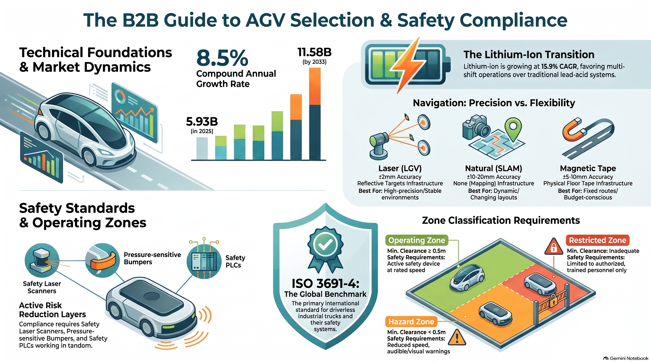
ISO 3691-4 is the Type C product-family standard for driverless industrial trucks. Its most practical contribution is a zone classification that ties physical clearance to speed limits and personnel-detection requirements:
| Zone | Clearance | Personnel detection | Max speed |
|---|---|---|---|
| Operating zone | ≥ 0.5 m width, ≥ 2.1 m height | Active, continuous | Rated design speed |
| Operating hazard zone | < 0.5 m on one/both sides | Active, continuous | Reduced, per the standard (≤ 0.3 m/s if detection is muted) |
| Restricted zone | < 0.5 m both sides, no escape | Active, dynamically mutable | ≤ 0.3 m/s with personnel present |
| Confined zone | No minimum | Deactivated | Unlimited (full fencing + interlocks) |
The 0.3 m/s figure appears repeatedly — it is the speed cap whenever personnel-detection means are muted, and it is the number that shapes the entire safety design. A forklift that must hand off a pallet at a conveyor dock mutes its scanner fields to avoid false trips, and in that moment its speed must drop to creep.
ISO 13849-1: the functional-safety core
ISO 13849-1 governs the Safety-Related Parts of Control Systems (SRP/CS). It quantifies safety as a Performance Level (PL), a band of dangerous-failure probability per hour:
| PL | PFHd (per hour) | Equivalent SIL |
|---|---|---|
| PL a | 10⁻⁵ to <10⁻⁴ | — |
| PL b | 3×10⁻⁶ to <10⁻⁵ | — |
| PL c | 10⁻⁶ to <3×10⁻⁶ | SIL 1 |
| PL d | 10⁻⁷ to <10⁻⁶ | SIL 2 |
| PL e | 10⁻⁸ to <10⁻⁷ | SIL 3 |
The PL is determined by four factors: the Category (architecture), MTTFd (mean time to dangerous failure), DCavg (diagnostic coverage), and CCF (common-cause failure). The architecture categories are the heart of the design:
| Category | Architecture | Fault tolerance | Max PL |
|---|---|---|---|
| B | Single channel | None | b |
| 1 | Single channel, well-tried components | None | c |
| 2 | Single channel + test | None | d |
| 3 | Dual channel | Single fault | e |
| 4 | Dual channel | Single fault + accumulation | e |
For an autonomous forklift, the target is almost always PL d, Category 3 — dual-channel, single-fault-tolerant, with cross-monitoring. ISO 3691-4 Table 1 maps the required PL per safety function:
| Safety function | Required PL | Category |
|---|---|---|
| Emergency stop (traction + brake) | PL d | 3 |
| Personnel detection (motive stop) | PL d | 3 or 4 |
| Dynamic speed monitoring | PL d | 3 |
| Braking system control | PL d | 3 or 4 |
| Parking brake control | PL b | 1 or 2 |
The hardware: what must be on the vehicle
The safety chain is built from certified components, each with a published safety figure:
| Component | Role | Typical part |
|---|---|---|
| Safety PLC | Runs the F-program, 1oo2-equivalent via coded processing | Siemens S7-1500F, Beckhoff TwinSAFE |
| Safety laser scanner | Personnel detection, protective field | SICK microScan3 Pro (Cat 3 / PL d) |
| Safety I/O | Dual-channel inputs, cross-circuit detection | ET 200SP F-DI |
| E-stop | Dual-channel NC, Category 0 stop | — |
| Light curtain | Zone monitoring at transfer stations | SICK deTec4, Keyence GL-R |
| Safety door switch | Interlock with locking | Schmersal AZM400 |
The scanner is the workhorse. A SICK microScan3 Pro carries a 275° aperture, Type 3 classification, Category 3 / PL d, and a PFH of 8×10⁻⁸ h⁻¹ — figures that feed directly into the SISTEMA calculation.
The software: F-CPU and the safety program
The software architecture is where most teams go wrong. The safety logic does not live in the same program as the navigation stack. It lives in a separate safety program on a fail-safe CPU (F-CPU), with its own memory area, its own I/O, and its own fieldbus.
flowchart LR
    subgraph FCPU["F-CPU — safety program (independent)"]
        IN["Dual-channel inputs<br/>E-stop, scanner OSSD, door switch"]
        FP["F-program<br/>demand latches, monitored reset"]
        OUT["F-DO outputs<br/>STO, brake, contactor"]
    end
    subgraph STD["Standard program"]
        NAV["Navigation, teleop,<br/>process interlocks"]
    end
    IN --> FP --> OUT
    NAV -.->|"read-only mirrors"| FP
Three principles are non-negotiable:
- Safety never traverses the network. No safety function uses MQTT, OPC UA, or Wi-Fi. The safety path is hardwired copper and PROFIsafe.
- The safety program stays correct if the standard program halts. Every safety function must reach its safe state with the standard CPU stopped.
- Wire NC, program NO. Safety devices are wired normally-closed and read as normally-open. A broken wire, unplugged connector, or dead sensor drops the signal to the tripped state — the fault stops the machine instead of masking the demand.
The safety fieldbus is PROFIsafe, running over standard PROFINET on the "black channel" principle. It protects against communication failure with four mechanisms: consecutive sequence numbering, unique safety addressing, an F-watchdog timer, and a 24-bit CRC. If a valid safety telegram does not arrive within the watchdog window, the receiving module passivates its outputs and the vehicle stops.
The reset behavior is equally strict. After any latched safety stop, restart requires a monitored, edge-triggered reset — a deliberate button press held between 0.2 s and 3 s, released on the falling edge. A stuck or bridged button never counts. And the reset clears latches only; it never starts motion.
The certification roadmap
The full path from concept to CE mark is a sequence of documented steps:
flowchart TD
    A["ISO 12100 risk assessment<br/>hazards, PLr targets"] --> B["SISTEMA loop modeling<br/>MTTFd, DCavg, CCF → PFHd"]
    B --> C["Functional & diagnostic testing<br/>discrepancy, cross-circuit, e-stop"]
    C --> D["Physical field validation<br/>Test A/B body detection, braking distance"]
    D --> E["Technical Construction File<br/>drawings, calculations, test logs"]
    E --> F["EU Declaration of Conformity<br/>+ CE plate"]
The SISTEMA step is where the math happens. Safety engineers model each loop — input, logic, output — and import the component reliability parameters (B10d, MTTFd, DC) from manufacturer libraries to calculate the system PFHd and verify it meets the PLr target.
Physical validation is done on-site, on the real floor. Test A and Test B place standardized low-reflectivity reference bodies (per the ISO 3691-4 annex) in the vehicle's path to confirm the scanner triggers a stop before contact. Dynamic braking validation loads the forklift to maximum payload, drives it at maximum speed, and measures the actual stopping distance against the protective field boundary.
Finally, the Technical Construction File compiles everything — drawings, schematics, risk assessment, SISTEMA logs, test reports, and a German-language user manual — and the manufacturer signs the EU Declaration of Conformity and affixes the CE plate.
What this means in practice
The recurring theme is separation. Safety is separated from the network, from the navigation stack, from the standard program. Every safety reaction must be executable with the network dead and the standard program halted.
And there is a hard honesty boundary worth stating plainly: a simulation can demonstrate the architecture — the separation of concerns, the latching logic, the reset behavior — but it cannot claim an achieved PL, a certified SIL, or a validated stopping distance. Those numbers come only from real hardware, real component data, and a real risk assessment. The gap between "designed to PL d" and "certified to PL d" is the entire certification procedure.
For a team building an autonomous forklift, the message is simple: start with the risk assessment, not the autonomy stack. The zones, the speed caps, the PL targets, and the hardware choices all flow from it. Get that wrong, and the most elegant navigation code in the world still cannot put the vehicle on the floor.
This post draws on the ISO 13849-1, ISO 12100, ISO 3691-4, IEC 62061, and Machinery Regulation (EU) 2023/1230 frameworks, plus the DGUV Vorschrift 68 and VDMA FTS guidelines that govern operation in Germany.
Next: Part 2 — Certifying an Autonomous Forklift in the United States